Rheometers/Viscometer
A rheometer is a device used to measure the flow response of a liquid to an applied force. It differs from a viscometer in the way that it measures fluids which can not be defined by a single value of a viscosity. To track this response it has to measure more parameters than a viscometer. For non-newtonian fluids a rheometer is better at tracking the response of the fluid to the changes in shear rate as it is not linear as for newtonian fluids. This section will give a brief explanation of the rheometers that were considered for this projects and the merits behind the choices. The main motivations for the choice of rheometers/viscometer were:
- Cost
- Electrorheologically fitability
- Can measure non-newtonian fluid accuratley
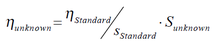
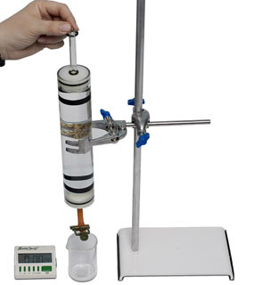
Falling Ball ViscometerThe falling ball viscometer works by measuring the time that a ball takes to fall between 2 points in the test liquid. The apparatus can be seen to the right. The ball is of known size, surface finish and weight. The dimensions of the cylinder are also known. This set up is cheap and simple but can only get results with relative values for non-newtonian fluids. The viscosity will be taken from a ratio with another fluid as seen below.
This system could be used to see differences between electric field "on" or "off" but would not provide absolute results of viscosity. When fitting an ER system a high voltage would be needed to create any size of electric field through the cylinder.For these reasons this method of measuring viscosity was discounted.
Rotational RheometerRotational rheometers run by measuring the spinning of a rotor over a stator with the measurement fluid in between them.The rotating surface rotates next to a stationary surface shearing the measurement fluid in between them. The resistance created by the shearing of the fluid is measured either as a torque at a measured speed, as a reduction in speed at a measured torque or both with controlled deformation. Rotational rheometers either control the speed and measure the torque, control the torque and measure the speed or control the deformation and measure both. The two different set-ups can be seen to the right. The third set up is a combination of the two.
The stator and rotor can take many forms for different applications. Three of the most commonly used geometries used in rotatational reometry can be seen below. (A) is a coaxial cylinder set up (B) is a Cone on plate set up (C) is a plate on plate set up. 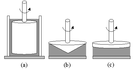
|
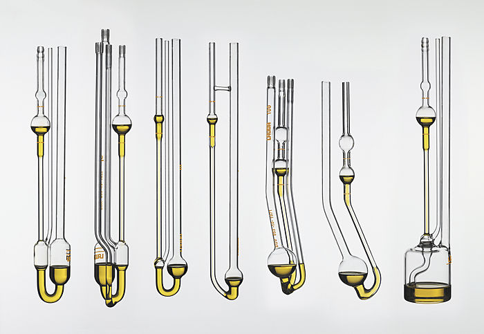
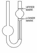
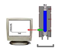
Capillary Viscometer/RheometerCapillary viscometers come in many different shapes and sizes but they work in essentially the same way. A reservoir of the test liquid is filled with an upper and lower line marking a known volume. Below the reservoir there is a restriction which the fluid passes through. The time is taken for the liquid to move from upper marker to lower marker and a viscosity is calculated using a capillary constant supplied with the viscometer. These viscometers can be gravitiy or pressure driven. These viscometers are simular to the falling ball viscometer and will only measure relative values but absolute values can be obtained by using the Rabinowitch equation which corrects for the non-newtonian properties of the fluid. Similar to the falling ball viscometer a large voltage would be needed to create a sufficient electric field through the liquid in the capillary.
Capillary rheometers exist also but are very expensive are were not considered as they were from the outset too expensive. 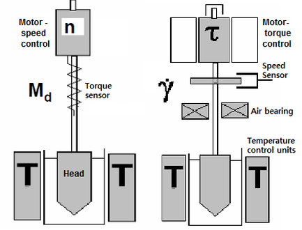
Rotational rheometers are very expensive but the university owns a unit which made this a good choice for doing the experiment on. The main challenge is creating a ER set up which will not risk damaging the rheometer. This will be discussed in the apparatus section of the website. With rotational rheometers, there is an abundance of different heads for different applications. The cone on plate rheometer was not applicable as the electric field would move from the point taking the path of least resistance. For accuracy of reading the coaxial cylinder is a better option as the shear rate is contant across its moving surfaces. The manufacturing of this part has many more levels of complexity as both the bath and the bob have to be aligned to very tight tolerances. Weight was also a big issue when making the part out of stainless steal. The plate on plate only required the manufacturing of the head and can be produced easier with no weight problem.For these reason the plate on plate option was chosen.
|